Fire pump capacity calculation किसी भी fire hydrant या sprinkler system की सबसे महत्वपूर्ण engineering step होती है। अगर pump सही calculate और select नहीं किया गया तो emergency के समय system required pressure और water flow deliver नहीं कर पाएगा।
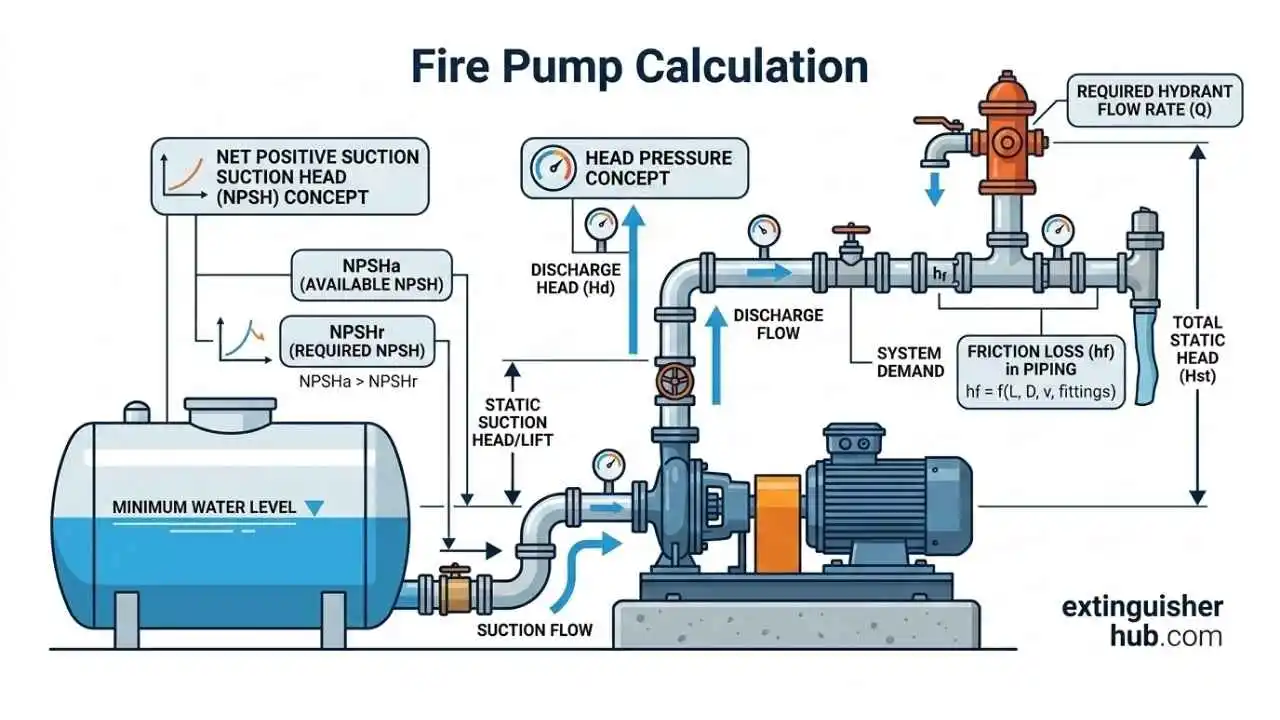
Fire pump selection केवल flow (LPM) पर आधारित नहीं होता। सही design में static head, friction loss, residual pressure और suction lift जैसे hydraulic factors शामिल होते हैं।
साथ ही suction side का critical parameter NPSH (Net Positive Suction Head) भी बहुत important होता है। NPSH यह सुनिश्चित करता है कि pump suction पर पर्याप्त pressure मौजूद हो और पानी vapor bubbles न बनाए। अगर NPSH margin कम हो जाए तो cavitation हो सकती है जिससे vibration, noise और pump damage का risk बढ़ जाता है — खासकर Indian summer (35–40°C) या high altitude locations में।
इस guide में आप सीखेंगे कि IS 15301 और NBC Part-4 के अनुसार fire pump capacity calculation कैसे किया जाता है, pump head formula कैसे apply किया जाता है और pipe velocity limit (5–7 m/s) को कैसे verify किया जाता है।
Fire Pump Selection गलत होने पर क्या होता है?
Real Indian Case Study (Pune Building Example)
Pune की एक commercial building inspection के दौरान fire hydrant system test किया गया। Pump running होने के बावजूद top floor hydrant पर required pressure achieve नहीं हो रहा था। Investigation में पता चला कि pump selection केवल LPM capacity देखकर किया गया था, जबकि static head और friction loss calculation सही तरीके से नहीं किया गया था।
Wrong Pump Selection के Major Impact
- Top floor hydrant pressure only 1.8 bar
- Fire department NOC rejection
- ₹4–5 lakh system modification cost
Core Engineering Principle
Fire pump selection = Flow + Head + NPSH + Velocity
Not just LPM.
Fire Pump क्या है? (Quick Technical Overview)
Fire Pump fire protection system का मुख्य hydraulic component होता है जो fire hydrant या sprinkler network में required pressure और water flow maintain करता है। जब system pressure drop होता है, तो fire pump automatically start होकर fire fighting network में pressurized water supply प्रदान करता है।
Fire Pump vs Jockey Pump Comparison
Fire protection system में Fire Pump और Jockey Pump दोनों अलग-अलग purpose के लिए design किए जाते हैं। Fire pump emergency firefighting के समय high flow water supply देता है, जबकि jockey pump system pressure maintain करता है ताकि main pump unnecessary start न हो।
| Parameter | Fire Pump | Jockey Pump |
|---|---|---|
| Purpose | Fire fighting water supply | System pressure maintain करना |
| Capacity | 100% system demand | 3–5% of main pump capacity |
| Operation | Emergency fire condition | Frequent short operation |
| Role | Main firefighting pump | Pressure stabilizer |
Jockey pump की working और pressure control logic को समझने के लिए यह guide पढ़ें:
Jockey Pump – Working & Pressure Maintenance Guide
Electric Fire Pump vs Diesel Fire Pump
| Parameter | Electric Fire Pump | Diesel Fire Pump |
|---|---|---|
| Role | Main fire pump | Standby backup pump |
| Power Source | Electric supply | Diesel engine |
| Start Method | Pressure drop auto start | Power failure या pressure drop |
| Standard | IS 15301 compliant | IS 15301 mandatory backup |
IS 15301 के अनुसार diesel fire pump की capacity electric pump के बराबर होनी चाहिए ताकि power failure की स्थिति में system full capacity से operate कर सके।
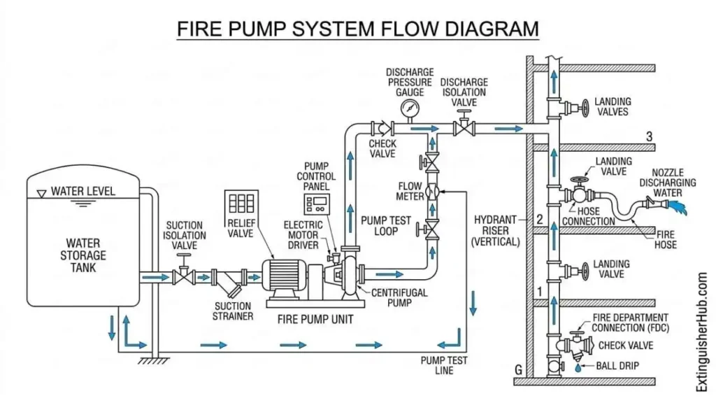
Fire Pump System Flow Diagram
Fire fighting system में water flow का basic sequence इस प्रकार होता है:
Fire Water Tank → Suction Pipe → Fire Pump → Discharge Header → Riser → Landing Valve → Fire Hose → Nozzle
यह पूरा hydraulic network building के Fire Hydrant System का हिस्सा होता है जो fire emergency में high pressure water discharge provide करता है।
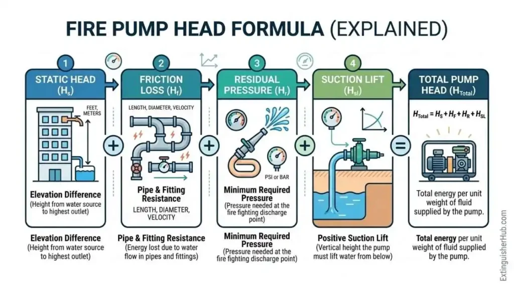
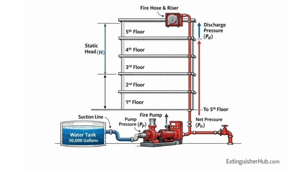
Fire Pump Head Formula (Core Concept)
Fire fighting system में pump selection करते समय सबसे महत्वपूर्ण calculation pump head का होता है। Pump head यह निर्धारित करता है कि pump hydrant network में required pressure और water flow maintain कर पाएगा या नहीं। इसलिए fire pump capacity calculation में head calculation को समझना जरूरी है।
Pump Head Calculation Formula
Static Head
+ Friction Loss
+ Residual Pressure
+ Suction Lift
इस formula में हर component hydraulic system के अलग-अलग pressure losses को represent करता है। Static head building height पर depend करता है, जबकि friction loss piping network की length, diameter और fittings के कारण increase होता है।
Final Design Head Calculation
Engineering practice में calculated pump head पर लगभग 10–15% safety factor apply किया जाता है। यह safety margin future pipe ageing, minor calculation error और system expansion को compensate करने में मदद करता है।
Fire pump design करते समय head calculation को हमेशा NBC Part-4 fire protection guidelines के अनुसार verify करना चाहिए। Official reference के लिए BIS portal देखें:
🌍 NBC Part-4 Fire Protection Guidelines – BIS Official
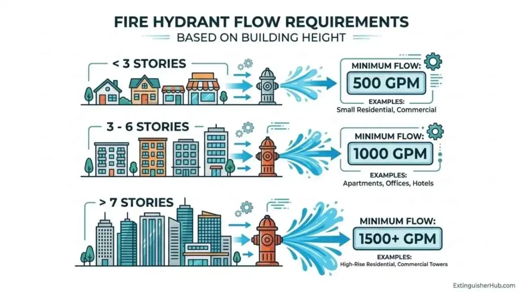
Step 1 – Flow Requirement Calculation (NBC Based)
Fire pump capacity calculation का पहला step होता है required fire water flow determine करना। यह value building height और hazard classification के आधार पर National Building Code (NBC Part-4) में define की गई है।
NBC Table 7 – Hydrant Flow Requirement
| Building Height | Required Fire Flow | Hydrants Operating |
|---|---|---|
| Up to 15 m | 180 LPM | 1 Hydrant |
| 15 m – 35 m | 2280 LPM | 2 Hydrants |
| Above 35 m | 2850 LPM | 2+ Hydrants |
NBC fire protection requirements के अनुसार hydrant system को इस प्रकार design किया जाता है कि required number of hydrants एक साथ operate कर सकें। Official reference के लिए देखें:
🌍 National Building Code – Fire Protection Guidelines
Simultaneous Hydrant Operation Rule
NBC guidelines के अनुसार hydrant system को इस प्रकार design किया जाना चाहिए कि कम से कम दो hydrants एक साथ operate कर सकें और required pressure maintain रहे।
Hydrant valve और hose connection के working principle को समझने के लिए यह guide पढ़ें:
Fire Hydrant Valve – Types & Working Guide
Fire fighting system design करते समय हमेशा simultaneous hydrant operation consider किया जाता है, क्योंकि emergency situation में multiple hoses एक साथ operate हो सकते हैं।
Example Calculation – Two Hydrants Operating
अगर दो hydrants एक साथ operate हो रहे हैं और एक hydrant के लिए average flow requirement लगभग 900 LPM माना जाए, तो total flow requirement इस प्रकार होगी:
Total Flow = Number of Hydrants × Flow per Hydrant
Example:
2 Hydrants × 900 LPM = 1800 LPM
लेकिन practical design में NBC Table-7 value को follow करना चाहिए। इसलिए 15–35 m building category में fire pump capacity लगभग 2280 LPM select की जाती है।
Step 2 – Residual Pressure Requirement
Fire hydrant system design करते समय यह सुनिश्चित करना जरूरी होता है कि सबसे दूर वाले hydrant point पर भी sufficient water pressure उपलब्ध हो। इस pressure को Residual Pressure कहा जाता है। NBC Part-4 guidelines के अनुसार यह pressure building hazard category पर depend करता है।
Minimum Pressure Requirement by Hazard Level
| Hazard | Minimum Pressure |
|---|---|
| Light Hazard | 3.5 bar |
| Ordinary Hazard | 4.2 bar |
Residual pressure का मतलब है कि hydrant valve open होने के बाद भी system में minimum required pressure बना रहना चाहिए। अगर pressure इससे कम हो जाए तो water discharge effective नहीं रहेगा।
Hydraulically Remote Point Concept
Hydrant system design में Hydraulically Remote Point वह location होती है जहाँ water pressure सबसे कम होने की संभावना होती है। यह point आमतौर पर building का सबसे ऊँचा floor या piping network का सबसे दूर का hydrant होता है।
Pump head calculation करते समय friction loss, pipe length और elevation को ध्यान में रखते हुए यह सुनिश्चित किया जाता है कि इस remote hydrant point पर भी required residual pressure उपलब्ध रहे।
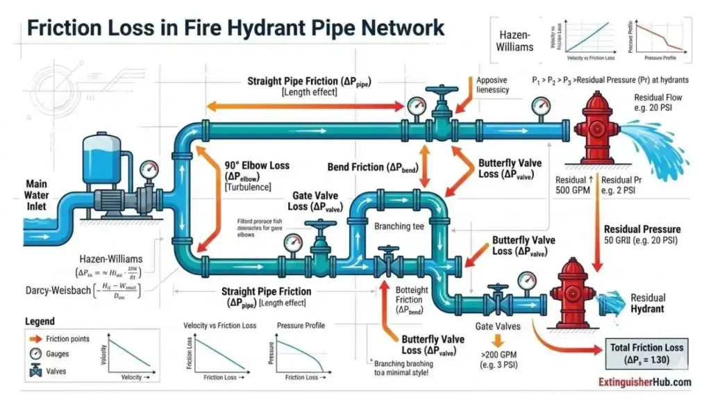
Step 3 – Friction Loss Calculation (Pipe Network)
Fire hydrant system और fire pump capacity calculation में friction loss एक महत्वपूर्ण factor होता है। जब water pipe network के अंदर flow करता है, तो pipe wall friction, bends, valves और fittings के कारण pressure drop होता है। इसी pressure loss को friction loss कहा जाता है।
अगर friction loss सही calculate नहीं किया गया तो fire pump required pressure maintain नहीं कर पाएगा और hydrant system का performance प्रभावित हो सकता है। इसीलिए fire pump head calculation में friction loss को हमेशा include किया जाता है।
Hazen-Williams Formula
Pipe network में friction loss calculate करने के लिए Hazen-Williams formula
Formula:
hL = 10.67 × L × Q1.85 / (C1.85 × d4.87)
जहाँ:
- hL = friction head loss (meter)
- L = pipe length (meter)
- Q = water flow rate
- C = Hazen-Williams coefficient
- d = pipe diameter
Fire pump capacity calculation करते समय friction loss जितना ज्यादा होगा, pump head requirement उतनी ही बढ़ेगी। इसलिए pipe size selection और pipe condition बहुत महत्वपूर्ण होती है।
Hydraulic calculation method के बारे में international reference यहाँ देखें:
🌍 NFPA Hydraulic Calculation Reference
Pipe Age Impact on Friction Loss
Pipe network की age बढ़ने के साथ pipe की internal surface rough हो जाती है। Rust, scale और deposits के कारण friction loss बढ़ जाता है। इसलिए fire pump capacity calculation करते समय pipe age को भी consider करना चाहिए।
| Pipe Age | Recommended C-Factor |
|---|---|
| New Pipe | 120 |
| 10 Years Old Pipe | 95 – 100 |
| 15+ Years Old Pipe | 85 – 90 |
Fire pump head calculation करते समय engineers अक्सर C-Factor = 120C-Factor 95–100
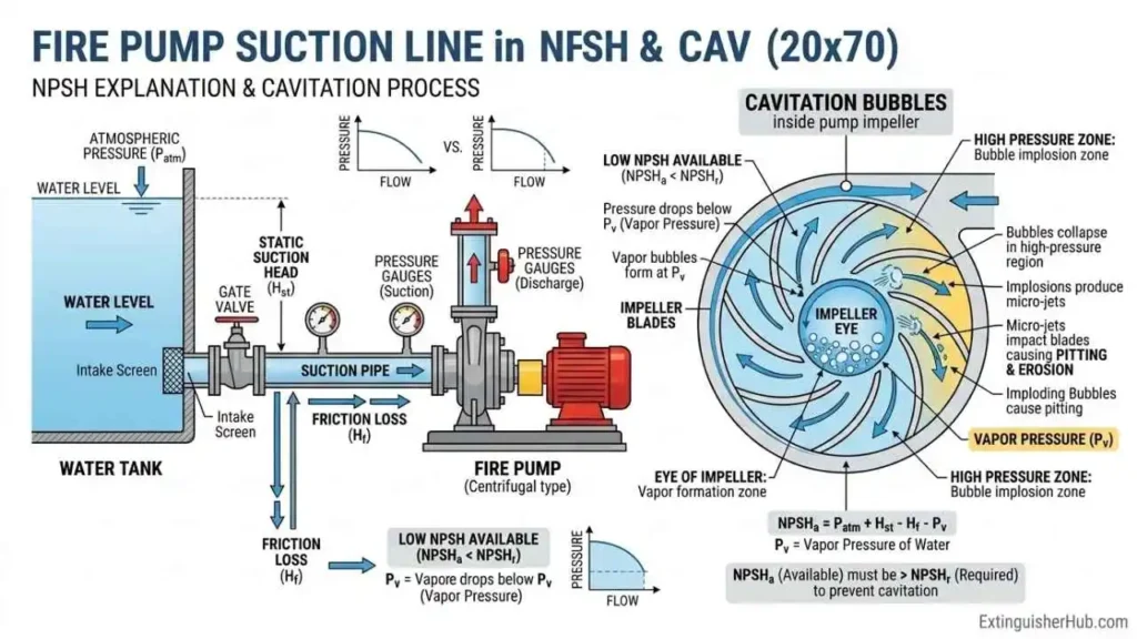
Suction Side Safety – NPSH, Temperature & Altitude
Fire pump capacity calculation करते समय suction side conditions को ignore करना एक common engineering mistake है। अगर suction pressure कम हो जाए तो pump के अंदर cavitation हो सकता है जिससे pump damage, vibration और performance loss जैसी समस्याएँ पैदा हो सकती हैं। इसीलिए fire pump design में NPSH, water temperature और altitude को ध्यान में रखना जरूरी होता है।
NPSH (Net Positive Suction Head) क्या है?
NPSH का मतलब है कि pump suction point पर available pressure vapor pressure से कितना ज्यादा है। अगर available pressure कम हो गया तो water vapor bubbles बनने लगते हैं जिसे cavitation कहा जाता है।
इसलिए fire pump selection करते समय यह सुनिश्चित किया जाता है कि NPSH available हमेशा NPSH required से ज्यादा हो। यह calculation fire pump capacity calculation का महत्वपूर्ण हिस्सा होता है।
Water Temperature Effect (Indian Summer)
India में summer season के दौरान water temperature काफी बढ़ सकता है, खासकर overhead tanks में। जब water temperature बढ़ता है तो vapor pressure भी बढ़ जाता है जिससे NPSH margin कम हो सकता है।
Example के लिए अगर water temperature 40°C तक पहुंच जाए, तो cavitation का risk बढ़ सकता है। इसलिए practical fire pump design में engineers summer temperature condition को भी consider करते हैं।
Altitude Impact (Pune / Shimla Example)
Altitude भी suction pressure को प्रभावित करता है। जैसे-जैसे altitude बढ़ता है atmospheric pressure कम होता जाता है। इससे pump suction side pressure भी कम हो सकता है।
उदाहरण के लिए:
- Pune (≈560 m altitude) – Atmospheric pressure थोड़ा कम
- Shimla (≈2200 m altitude) – Pressure काफी कम
इसलिए hill stations या high altitude locations में fire pump capacity calculation करते समय suction margin थोड़ा ज्यादा रखा जाता है।
Minimum Safe NPSH Margin
Engineering practice के अनुसार NPSH available हमेशा NPSH required से कम से कम 0.5 meter ज्यादा होना चाहिए। यह safety margin cavitation risk को कम करने में मदद करता है।
Fire pump installation करते समय suction pipe को possible हो तो short और straight रखा जाना चाहिए। Extra bends और valves friction loss बढ़ाते हैं जिससे NPSH margin कम हो सकता है।
Hydraulic pump design standards के बारे में detailed reference यहाँ देखें:
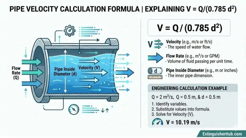
Velocity Check (IS 15301 Requirement)
Fire hydrant system और fire pump capacity calculation में pipe velocity check करना बहुत जरूरी होता है। अगर water velocity बहुत ज्यादा हो जाए तो pipe vibration, noise, water hammer और friction loss बढ़ सकता है। इसीलिए IS 15301 standard pipe velocity limit specify करता है।
Velocity Calculation Formula
जहाँ:
- V = water velocity (m/s)
- Q = water flow rate (m³/s)
- d = pipe diameter (meter)
Fire pump head calculation करते समय friction loss के साथ-साथ pipe velocity को भी verify किया जाता है ताकि system safe limit में operate करे।
Recommended Velocity Limit
IS 15301 standard के अनुसार fire fighting piping system में recommended velocity limit निम्न प्रकार होती है:
Minimum: 5 m/s
Maximum: 7 m/s
अगर pipe velocity 7 m/s से ज्यादा हो जाती है तो friction loss काफी बढ़ सकता है और system efficiency कम हो सकती है। इसलिए fire pump capacity calculation करते समय pipe diameter इस प्रकार select किया जाता है कि velocity safe limit में रहे।
Example Velocity Calculation
मान लीजिए hydrant system में water flow 2400 LPM है और pipe diameter 100 mm है। तब velocity calculation इस प्रकार होगी:
| Parameter | Value |
|---|---|
| Flow Rate (Q) | 2400 LPM = 0.04 m³/s |
| Pipe Diameter (d) | 100 mm = 0.1 m |
| Velocity (V) | ≈ 5.09 m/s |
इस example में velocity लगभग 5.09 m/s आती है, जो IS 15301 recommended range (5–7 m/s) के अंदर है। इसलिए यह pipe size hydrant system के लिए acceptable माना जाएगा।
Complete Worked Example – Fire Pump Calculation
Fire pump capacity calculation को बेहतर समझने के लिए एक practical example देखते हैं। यह example एक 5-storey commercial building के fire hydrant system design पर आधारित है।
Project Details (5-Storey Commercial Building)
| Parameter | Value |
|---|---|
| Building Type | Commercial Building |
| Number of Floors | 5 Floors |
| Building Height | 22 m |
| Hazard Category | Ordinary Hazard |
Step 1 – Flow Requirement
NBC Part-4 के अनुसार 15–35 meter height building के लिए hydrant system flow requirement लगभग 2280 LPM होती है।
Step 2 – Static Head Calculation
Static head building height के बराबर होता है। यह pump को overcome करना पड़ता है ताकि water top floor तक पहुंच सके।
Step 3 – Friction Loss Calculation
Pipe network, bends, valves और fittings के कारण pressure drop होता है जिसे friction loss कहा जाता है। Practical fire hydrant design में friction loss लगभग 8 meter माना जा सकता है।
Step 4 – Suction Lift Calculation
अगर water tank pump level से नीचे है तो suction lift consider किया जाता है।
Final Pump Head Result
अब total pump head calculate करते हैं:
Practical design में 10–15% safety factor apply किया जाता है ताकि future pipe ageing और calculation error compensate हो सके।
Motor Power Selection
Pump motor power selection flow rate और pump head पर depend करता है।
Fire pump commissioning और performance testing के step-by-step process को समझने के लिए यह guide देखें:
8 Critical Fire Pump Selection Mistakes
Fire pump capacity calculation करते समय कई बार design engineers कुछ महत्वपूर्ण factors को ignore कर देते हैं। इन गलतियों के कारण fire hydrant system emergency के समय proper pressure और flow provide नहीं कर पाता। नीचे fire pump selection में होने वाली सबसे common mistakes दी गई हैं।
Mistake 1 – Only Flow Consider करना
कई projects में pump selection केवल LPM (flow) देखकर किया जाता है। लेकिन fire pump design में flow के साथ-साथ pump head भी equally important होता है। अगर head calculation सही नहीं किया गया तो hydrant pressure कम हो सकता है।
Mistake 2 – Static Head Ignore करना
Building height के कारण water को top floor तक पहुंचाने के लिए pump को extra pressure generate करना पड़ता है। अगर static head calculation ignore कर दिया जाए तो hydrant system required pressure maintain नहीं कर पाएगा।
Mistake 3 – Friction Loss Underestimate करना
Pipe length, bends, valves और fittings के कारण pressure drop होता है जिसे friction loss कहा जाता है। अगर friction loss कम assume किया गया तो fire pump capacity calculation inaccurate हो सकती है।
Mistake 4 – NPSH Margin Ignore करना
Pump suction side पर sufficient pressure maintain करना जरूरी होता है। अगर NPSH margin कम हुआ तो cavitation हो सकता है, जिससे pump damage और vibration की समस्या पैदा हो सकती है।
Mistake 5 – Pipe Diameter Wrong Select करना
अगर pipe diameter छोटा select किया गया तो water velocity बढ़ जाती है। इससे friction loss बढ़ता है और hydrant pressure कम हो सकता है। इसलिए pipe size selection hydraulic calculation के आधार पर करना चाहिए।
Mistake 6 – Pump Oversizing
कई बार engineers safety के लिए unnecessarily large pump select कर लेते हैं। Oversized pump energy consumption बढ़ाता है और system pressure control करना भी मुश्किल हो सकता है।
Mistake 7 – Diesel Backup Incorrect
IS 15301 के अनुसार diesel fire pump की capacity electric fire pump के बराबर होनी चाहिए। अगर diesel pump छोटा रखा गया तो power failure के समय system required performance नहीं दे पाएगा।
Mistake 8 – No Regular Testing
Fire pump installation के बाद regular testing और maintenance बहुत जरूरी होता है। अगर pump system का periodic testing नहीं किया गया तो emergency situation में system fail हो सकता है।
Fire protection system की reliability बनाए रखने के लिए regular inspection और fire safety audit करना जरूरी है। Detailed checklist के लिए यह guide देखें:
👉 Fire Safety Audit Checklist Guide
Pump Selection Criteria (IS 15301 Based)
Fire pump capacity calculation के बाद अगला महत्वपूर्ण step pump selection होता है। Pump selection करते समय flow requirement, pump head, motor power और backup arrangement जैसे factors को ध्यान में रखा जाता है। IS 15301 standard fire pump installation और selection के basic guidelines provide करता है।
Fire Pump Types Comparison
Fire fighting system में अलग-अलग types के pumps use किए जाते हैं। Pump type selection building height, space availability और system design पर depend करता है।
| Pump Type | Best Application | Main Advantage |
|---|---|---|
| Horizontal Split Case | Commercial buildings | High efficiency और easy maintenance |
| Vertical Turbine Pump | High-rise buildings | High pressure capability |
| End Suction Pump | Small fire systems | Compact design और low cost |
Diesel Backup Requirement
Fire protection system में power failure की स्थिति को ध्यान में रखते हुए diesel fire pump mandatory backup के रूप में install किया जाता है।
Diesel fire pump capacity electric fire pump के बराबर (100%) होनी चाहिए ताकि emergency के समय system required pressure और flow maintain कर सके।
Diesel engine driven pump automatic start mechanism के साथ install किया जाता है ताकि electricity failure की स्थिति में hydrant system तुरंत operate हो सके।
Electric Motor Power Formula
Fire pump motor power calculation pump flow rate और pump head पर depend करता है।
जहाँ:
- P = Motor Power (kW)
- Q = Flow Rate (m³/hr)
- H = Pump Head (meter)
- η = Pump Efficiency
Fire pump capacity calculation के बाद इसी formula का उपयोग करके appropriate motor rating select की जाती है।
What Fire Inspectors Check During Flow Test
Fire pump installation के बाद fire department या safety inspector system performance verify करने के लिए flow test करते हैं। इस test के दौरान यह सुनिश्चित किया जाता है कि fire pump required pressure और water flow deliver कर रहा है या नहीं।
नीचे कुछ महत्वपूर्ण checks दिए गए हैं जो inspectors flow testing के दौरान verify करते हैं।
Auto Start Test
Hydrant valve open करके system pressure intentionally drop किया जाता है। अगर pressure drop होते ही fire pump automatically start हो जाए तो auto-start mechanism सही माना जाता है।
Pressure Stability Check
Pump running condition में discharge pressure gauge observe किया जाता है। Pressure stable रहना चाहिए और sudden fluctuation नहीं होना चाहिए।
Cavitation Noise Detection
Inspector pump running sound भी observe करता है। अगर pump के अंदर gravel या rattling जैसी आवाज आए तो यह cavitation का संकेत हो सकता है। यह suction side problem या insufficient NPSH का result हो सकता है।
Diesel Pump Start Test
Power supply disconnect करके diesel pump auto start test किया जाता है। Diesel engine को short time में start होकर system pressure build करना चाहिए।
Documentation Verification
- Fire pump testing logbook
- Weekly testing records
- Maintenance and servicing reports
- System commissioning certificate
Proper documentation maintain करना fire safety compliance का महत्वपूर्ण हिस्सा है और audit के समय यह records verify किए जाते हैं।
Regular fire pump testing और system inspection hydrant system reliability maintain करने के लिए बहुत जरूरी होता है। Weekly testing और periodic maintenance system failure risk को काफी कम कर देते हैं।
Fire Pump Commissioning & Testing Checklist
Fire pump installation complete होने के बाद system को commissioning test से गुजरना पड़ता है। इस प्रक्रिया में pump performance, pressure stability और automatic operation verify किया जाता है ताकि fire hydrant system emergency के समय सही तरीके से काम कर सके।
Pre-Commissioning Inspection
- Pump और motor alignment check करना
- Suction और discharge valves की position verify करना
- Electrical connections और control panel inspection
- Lubrication oil level और bearing condition check करना
- Pressure gauges और sensors की working verify करना
Pressure Test
Hydrant piping network का pressure test किया जाता है ताकि यह verify किया जा सके कि piping system leak-proof है।
- Hydrostatic pressure test perform करना
- Working pressure से लगभग 1.5× pressure apply करना
- Pipe joints और valves में leakage check करना
Flow Test
Flow test के दौरान pump को operate करके actual water flow और discharge pressure measure किया जाता है।
- Hydrant outlet open करके pump run करना
- Flow meter या calibrated nozzle से flow measure करना
- Pressure gauge reading record करना
Auto Start Testing
Fire pump system का auto start mechanism test किया जाता है। जब system pressure drop होता है तो pump automatically start होना चाहिए।
- Hydrant valve open करके pressure drop create करना
- Pump auto start time observe करना
- Jockey pump और main pump sequence verify करना
Commissioning के बाद fire pump system का weekly testing schedule maintain करना चाहिए। Regular testing से pump reliability improve होती है और emergency situation में system failure का risk कम हो जाता है।
Detailed step-by-step testing process के लिए यह practical guide पढ़ें:
👉
Fire Pump Testing Steps – Complete Guide
Frequently Asked Questions
Fire pump capacity calculation कैसे करें?
Fire pump capacity calculation करने के लिए सबसे पहले building height और hazard category के अनुसार NBC Part-4 से required flow (LPM) निर्धारित किया जाता है। इसके बाद pump head calculate किया जाता है जिसमें static head, friction loss, residual pressure और suction lift शामिल होते हैं। इन सभी values को जोड़कर final pump head मिलता है और उसी के आधार पर fire pump capacity select की जाती है।
Fire pump head formula क्या है?
Fire pump head calculate करने का basic formula है:Pump Head = Static Head + Friction Loss + Residual Pressure + Suction Lift
150% Flow Rule क्या होता है?
Fire pump को rated flow के 150% तक water supply देने में सक्षम होना चाहिए ताकि emergency में multiple hydrants operate होने पर भी system काम कर सके।
NPSH क्यों important है?
NPSH pump suction side पर available pressure को दर्शाता है। अगर NPSH कम हो जाए तो pump में cavitation हो सकता है जिससे pump damage हो सकता है।
Fire pump velocity limit क्या है?
IS 15301 के अनुसार fire fighting pipe system में water velocity सामान्यतः 5–7 m/s के बीच रखी जाती है।
IS 15301 pump requirements क्या हैं?
IS 15301 fire fighting pumps की installation और maintenance के लिए guidelines देता है, जिसमें electric pump, diesel backup pump और jockey pump arrangement शामिल होता है।
Pump head safety factor कितना होना चाहिए?
Fire pump head calculation के बाद सामान्यतः 10–15% safety factor add किया जाता है ताकि system future conditions में भी reliable रहे।
My Final Thoughts – Engineering Mindset
Fire pump selection केवल equipment selection नहीं है, बल्कि यह एक complete hydraulic engineering process है। अगर fire pump capacity calculation सही तरीके से किया जाए तो fire hydrant system emergency के समय reliable water supply provide कर सकता है।
Hydraulic Calculation First
Fire pump design हमेशा proper hydraulic calculation से शुरू होना चाहिए। Flow requirement, pump head, friction loss, suction condition और pipe velocity जैसे factors को calculation में शामिल करना जरूरी है। अगर pump केवल catalogue देखकर select किया गया तो system performance प्रभावित हो सकता है।
Future-Proof Pump Design
Fire protection system कई वर्षों तक operate करता है। इसलिए pump design करते समय future pipe ageing, additional fittings और possible system expansion को ध्यान में रखना चाहिए। थोड़ा safety margin system reliability बढ़ाने में मदद करता है।
Compliance with IS 15301 & NBC
Fire pump installation और design हमेशा IS 15301 और NBC Part-4 fire protection guidelines के अनुसार होना चाहिए। इन standards का पालन करने से system safety, fire department approval और regulatory compliance सुनिश्चित होता है।
Documentation & Maintenance Importance
Fire protection system की reliability बनाए रखने के लिए proper documentation और maintenance जरूरी होता है। Weekly pump testing, inspection records और servicing reports maintain करने से system readiness हमेशा verify की जा सकती है।
एक अच्छी fire protection design philosophy यह है कि system को इस तरह design किया जाए कि emergency के समय pump बिना किसी delay के required pressure और water flow deliver कर सके।
Trusted Sources & Technical References
Fire pump capacity calculation और fire protection system design हमेशा recognized engineering standards और technical references के आधार पर किया जाना चाहिए। नीचे दिए गए sources fire hydrant और fire pump system design के लिए widely accepted references हैं।
Indian Standards (BIS)
- IS 15301 – Installation and maintenance of fire fighting pumps
- IS 3844 – Internal hydrant and hose reel systems
- IS 13039 – External hydrant system installation
- IS 9668 – Water supply requirements for fire fighting
- IS 636 – Fire fighting hose specification
- IS 903 – Fire fighting branch pipe and nozzle
National Building Code (NBC India)
NBC Part-4 fire protection guidelines India में building fire safety design के लिए सबसे महत्वपूर्ण reference document है। Hydrant flow requirement, pressure limits और fire pump selection guidelines इसी code में define की गई हैं।
🌍 National Building Code – Fire Protection Guidelines (BIS Official)
International Fire Protection Standards
- NFPA 20 – Standard for Installation of Stationary Fire Pumps
- NFPA 14 – Standard for Standpipe and Hose Systems
- Hydraulic Institute Pump Standards
Technical Engineering References
- Hazen-Williams hydraulic calculation method
- Hydraulic Institute pump design guidelines
- Pump manufacturer technical manuals
- Fire protection engineering best practices
Fire pump capacity calculation और hydrant system design हमेशा applicable standards के अनुसार verify किया जाना चाहिए। Actual project design site-specific hydraulic calculations, pipe network layout और building fire load assessment पर depend करता है।

2 thoughts on “Fire Pump Capacity Calculation Guide (IS 15301 + NBC) – Head Formula, Flow, NPSH & 8 Critical Mistakes”