आग लगने की स्थिति में अगर fire pump चालू होने के बावजूद आग कंट्रोल नहीं होती, तो इसका कारण अक्सर fire hydrant system design, hydraulic calculation या maintenance में कमी होता है।
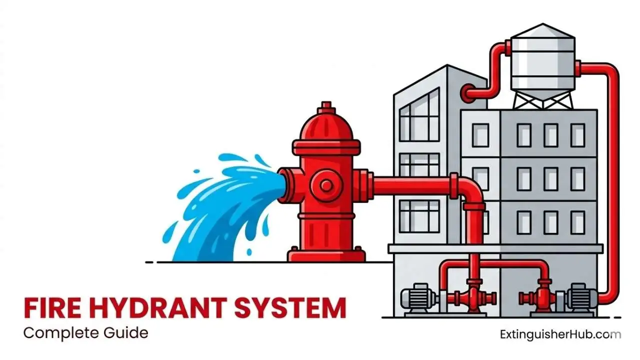
Fire Hydrant System एक engineered water-based fire protection system है जो pressurized water supply के माध्यम से firefighting के लिए उपयोग किया जाता है। इसमें fire pump, water storage tank, riser piping, hydrant valves और hose system शामिल होते हैं।
भारत में hydrant systems का design और installation IS 3844, IS 13039 और NBC Part-4 (Fire & Life Safety) के अनुसार किया जाता है। इन standards के अनुसार remote hydrant point पर required residual pressure बनाए रखना अनिवार्य होता है।
इस guide में हम hydrant system के types, basic hydraulic concepts, pressure requirements और practical design considerations को BIS और NBC guidelines के अनुसार समझेंगे।
Introduction – Fire Emergency में Hydrant System क्यों Critical है?
Pump सही होने पर भी System Perform क्यों नहीं करता?
अक्सर साइट पर fire pump चालू होता है और pressure gauge भी acceptable range दिखाता है, फिर भी आग प्रभावी रूप से नियंत्रित नहीं हो पाती। इसका कारण pump नहीं, बल्कि system design, hydraulic losses और maintenance gaps होते हैं।
- Incorrect hydraulic calculation: Pump head, static head और flow requirement का सही आकलन न होना
- Friction loss underestimation: Pipe length, bends, valves और fittings के कारण pressure drop को ignore करना
- Maintenance issues: Pump testing, valve operation और gauge calibration का नियमित निरीक्षण न होना
Typical Indian Industrial Scenario
कई भारतीय औद्योगिक प्रोजेक्ट्स में design drawings सही होते हैं, लेकिन site execution में undersized piping, dead-end नेटवर्क और improper pressure control system performance को प्रभावित करते हैं।
इस गाइड में हम क्या कवर करेंगे?
इस guide में hydrant system को NBC Part 4 और IS 3844 के संदर्भ में समझाया गया है:
- Fire hydrant system के types और applications
- Pressure और flow basics (NBC guidelines के अनुसार)
- Pump head concept और friction loss overview
- Common design mistakes और practical audit points
Fire Hydrant System क्या है?
Fire Hydrant System एक engineered water-based fire protection system है जो आग लगने की स्थिति में pressurized water supply प्रदान करता है। इस प्रणाली में fire pump, water storage tank, riser piping, landing valves, hose और nozzle शामिल होते हैं, जो मिलकर emergency firefighting के लिए water delivery सुनिश्चित करते हैं।
Engineered Water Distribution Concept
यह system सामान्य plumbing network नहीं होता, बल्कि hydraulic design principles के आधार पर तैयार किया जाता है। Static head, friction loss, flow requirement और residual pressure को ध्यान में रखकर पूरे system की piping layout और pump capacity निर्धारित की जाती है। Hydraulic design basics समझने के लिए देखें: Fire Pump Capacity Calculation Guide .
Pressurized Supply & Emergency Response
Hydrant system का उद्देश्य यह सुनिश्चित करना है कि building के किसी भी हिस्से में आग लगने पर required pressure और flow के साथ तुरंत पानी उपलब्ध हो। NBC Part 4 के अनुसार hydraulically remote outlet पर minimum residual pressure बनाए रखना आवश्यक होता है।
Short Working Overview (Voice Search Friendly)
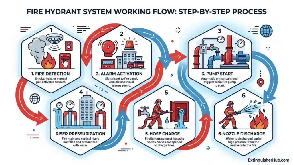
Fire emergency के दौरान fire pump start होकर riser system को pressurize करता है। Landing valve खोलने पर hose line charge होती है और nozzle के माध्यम से पानी fire area पर discharge किया जाता है।
Detailed Working Flow – Step-by-Step System Operation
Fire Detection से Pump Activation तक
जब building में fire detection system (detectors या manual call point) activate होता है, तो fire alarm system signal generate करता है। Hydrant system में pressure drop होने पर main electric fire pump automatically start होता है और riser network को pressurize करता है।
Jockey Pump की भूमिका
Jockey pump system pressure को normal condition में maintain करने के लिए उपयोग किया जाता है। यह small-capacity pump होता है जो minor leakage या pressure drop को compensate करता है, ताकि main fire pump unnecessary start न हो।
विस्तार से समझने के लिए देखें: fire fighting pump और jockey pump कैसे काम करते हैं
Diesel Pump Backup Logic
अगर electric power failure हो जाए या main pump operate न करे, तो diesel engine driven fire pump automatically start होता है। IS 15301 के अनुसार diesel pump की capacity और performance main fire pump के equivalent रखी जाती है ताकि emergency में continuous water supply बनी रहे।
Riser Pressurization से Nozzle Discharge तक Flow Sequence
- Fire pump पानी को riser piping network में pressurize करता है
- Fire fighter landing valve operate करता है
- Hose line charge होती है और required pressure प्राप्त करती है
- Nozzle के माध्यम से निर्धारित flow और pressure के साथ पानी discharge होता है
इस पूरी प्रक्रिया में hydraulic balance, सही pump head और NBC Part 4 के अनुसार required residual pressure बनाए रखना अत्यंत महत्वपूर्ण होता है।
फायर हाइड्रेंट सिस्टम कैसे काम करता है
Fire Hydrant System के मुख्य Components
Fire Water Tank (NBC Part 4 / IS 9668)
Fire water tank hydrant system का primary water source होता है। NBC Part-4 के अनुसार tank capacity hazard classification और fire demand पर निर्भर करती है। सामान्यतः storage capacity fire pump demand के अनुसार निर्धारित की जाती है (minimum duration as per NBC requirement)।
Main Electric Pump (IS 15301)
Main fire pump system को required pressure और flow प्रदान करता है। IS 15301 के अनुसार pump selection hydraulic calculation के आधार पर किया जाता है, जिसमें static head, friction loss और required residual pressure शामिल होते हैं।
Jockey Pump – Pressure Maintenance
Jockey pump system pressure को normal condition में maintain करता है। यह small-capacity pump minor leakage या pressure drop को compensate करता है, ताकि main fire pump unnecessary start न हो।
विस्तार से जानें: fire fighting pump और jockey pump कैसे काम करते हैं
Diesel Pump – Backup (IS 15301)
Power failure की स्थिति में diesel engine driven fire pump automatically operate होता है। IS 15301 के अनुसार diesel pump की capacity और performance main pump के equivalent रखी जाती है, ताकि emergency में uninterrupted water supply बनी रहे।
Landing Valve / Hydrant Valve (IS 3844)
Landing valve internal hydrant outlet होता है, जो प्रत्येक floor पर staircase या exit के पास स्थापित किया जाता है। IS 3844 के अनुसार hydrant coverage और spacing building layout के अनुसार निर्धारित की जाती है।
Yard Hydrant (IS 13039)
External yard hydrants open areas और industrial premises के लिए उपयोग किए जाते हैं। IS 13039 के अनुसार hydrant spacing site layout और coverage requirement के आधार पर निर्धारित की जाती है।
Hose Reel (IS 3844)
Hose reel first-aid firefighting के लिए उपयोग किया जाता है। यह quick response के लिए designed होता है और सामान्यतः small-bore hose के साथ install किया जाता है।
Piping Network (IS 3844)
Piping network पूरी प्रणाली का backbone होता है। Proper diameter selection, looped network configuration और hydraulic balancing system performance के लिए आवश्यक हैं। Flow velocity को design limits के भीतर रखना चाहिए ताकि pressure loss और water hammer effects नियंत्रित रहें।
Fire Hose (IS 636)
Fire hose water delivery medium होता है, जो landing valve से nozzle तक पानी पहुँचाता है। IS 636 के अनुसार hose का periodic inspection और testing आवश्यक होता है।
Nozzle / Branch Pipe (IS 903)
Nozzle पानी को controlled stream या spray pattern में discharge करता है। IS 903 के अनुसार nozzle selection required flow और pressure के अनुसार किया जाता है।
सही selection समझने के लिए पढ़ें: fire fighting nozzle types और selection guide
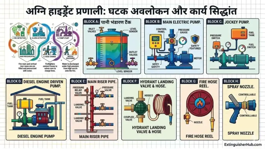
फायर हाइड्रेंट सिस्टम के मुख्य घटक
Types of Fire Hydrant Systems
Wet Riser System
Wet riser system में vertical riser पाइप हमेशा pressurized water से भरी रहती है। यह आमतौर पर high-rise buildings में उपयोग किया जाता है, ताकि प्रत्येक floor पर तुरंत water supply उपलब्ध हो सके (NBC Part 4 reference)।
Dry Riser System
Dry riser system सामान्यतः खाली रहता है और emergency के समय fire brigade द्वारा fire service inlet के माध्यम से pressurize किया जाता है। यह उन buildings में उपयोगी होता है जहाँ permanent internal pumping system उपलब्ध नहीं होता।
Down-Comer System
Down-comer system में terrace tank से gravity द्वारा पानी नीचे supply किया जाता है। इसमें प्रत्येक floor पर landing valves होते हैं। यह low-rise buildings में उपयोग किया जाता है जहाँ required pressure gravity से प्राप्त हो सकता है।
External Yard Hydrant System
External yard hydrant system industrial plants, tank farms और open areas में लगाया जाता है। IS 13039 के अनुसार hydrant spacing site layout और hazard classification के अनुसार निर्धारित की जाती है।
Internal Hydrant System
Internal hydrant system building के अंदर staircase या exit points के पास लगाया जाता है। IS 3844 के अनुसार hydrant coverage इस प्रकार design किया जाता है कि fire hose और jet reach के माध्यम से पूरे floor area को effectively cover किया जा सके।
Comparison Table – Type vs Use vs Standard
| Type | Typical Use | Key Feature | Applicable Standard |
|---|---|---|---|
| Wet Riser | High-rise buildings | Always pressurized, instant response | IS 3844 / NBC Part 4 |
| Dry Riser | Buildings without permanent pump system | Normally empty, brigade pressurized | NBC |
| Down-Comer | Low-rise buildings | Gravity-fed system | IS 3844 |
| External Yard | Industrial plants / open areas | Outdoor hydrant network | IS 13039 |
| Internal Hydrant | Building interiors | Landing valves near exits | IS 3844 |
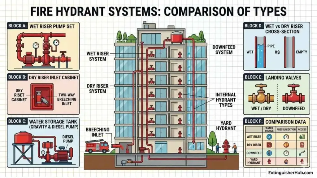
फायर हाइड्रेंट सिस्टम के प्रकार
Technical Core – Pressure & Flow Calculation (NBC & IS Based)
Required Residual Pressure
NBC Part-4 के अनुसार hydraulically most remote hydrant outlet पर minimum residual pressure बनाए रखना अनिवार्य है। यह pressure सुनिश्चित करता है कि effective jet throw और firefighting possible हो।
- Light Hazard: ≥ 3.5 bar
- Ordinary / High Hazard: ≥ 4.2 bar
Official reference: NBC Part-4 – BIS Official
Flow Requirement (IS 3844 Reference)
IS 3844 के अनुसार flow requirement building hazard और number of hydrants in operation पर निर्भर करती है। Design करते समय simultaneous hose streams को consider करना आवश्यक होता है। Exact flow value project-specific hydraulic calculation से निर्धारित की जाती है।
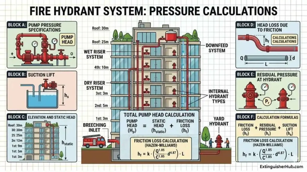
Pump Head Calculation Formula
Pump selection के लिए सभी head components का accurate estimation आवश्यक है। Minor losses में valves, bends, tees और fittings शामिल होते हैं।
Hazen-Williams Formula
जहाँ:
hL = Head loss (m)
L = Pipe length (m)
Q = Flow rate (L/s)
C = Roughness coefficient
d = Internal diameter (mm)
Recommended design velocity आमतौर पर ~1.5 से 3 m/s के बीच रखी जाती है, ताकि excessive friction loss और water hammer effects से बचा जा सके।
Field validation के लिए देखें: fire pump testing steps
Darcy-Weisbach Approach
Detailed hydraulic analysis और large industrial systems में Darcy-Weisbach equation का उपयोग किया जाता है। हालाँकि practical fire hydrant design में Hazen-Williams method अधिक common है।
Static Head – Worked Example
उदाहरण: यदि building height 30m है और required residual head ≈ 35m (3.5 bar) है, तो friction loss और minor losses जोड़कर total pump head निर्धारित किया जाता है।
फायर हाइड्रेंट सिस्टम प्रेशर कैलकुलेशन
Common Design Mistakes in Indian Projects (Field-Level Reality Check)
Pump की suction pipe का diameter कम रखना एक common mistake है। इससे cavitation risk बढ़ता है, NPSH margin कम हो जाता है और pump efficiency गिर जाती है। Result: Emergency में pump required discharge नहीं दे पाता।
Dead-end piping pressure imbalance और water hammer का कारण बनती है। Loop (ring main) network system reliability और uniform pressure distribution सुनिश्चित करता है।
Pressure Reducing Valve (PRV) गलत setting पर calibrated होने से upper floors पर insufficient pressure या lower floors पर excessive pressure problem होती है। Proper commissioning और periodic testing अनिवार्य है।
NBC Part-4 के अनुसार required fire water storage maintain न करने पर system duration और fire demand पूरी नहीं हो पाती। Emergency में water depletion system failure का कारण बन सकता है।
Pipe velocity को design limits से अधिक रखने पर friction loss, noise, vibration और water hammer risk बढ़ जाता है। सामान्यतः hydrant systems में velocity ~1.5 से 3 m/s के बीच रखना बेहतर माना जाता है।
Fire Hydrant System Design Standards (India Focus)
IS 3844 – Internal Hydrant Installation & Maintenance
IS 3844 standard building के अंदर hydrant और hose reel system की installation, layout, pressure requirement और maintenance guidelines define करता है। यह landing valve location और hydrant coverage को इस प्रकार define करता है कि hose length और jet reach के माध्यम से पूरे area को effectively cover किया जा सके।
IS 13039 – External Hydrant System
IS 13039 industrial premises और external yard hydrant system के design, hydrant spacing और water demand criteria को specify करता है। Hydrant spacing site layout, hazard category और coverage requirement के आधार पर तय की जाती है।
IS 15301 – Fire Pump Installation
IS 15301 fire fighting pumps की installation, testing और maintenance के लिए लागू होता है। इसमें electric pump, diesel pump और jockey pump arrangement, pump room layout, ventilation और periodic testing requirements शामिल हैं।
NBC Part-4 Overview
National Building Code (Part-4: Fire & Life Safety) भारत में fire protection systems के लिए primary guideline है। यह hydrant systems के लिए required residual pressure, water storage, fire demand और building classification-based requirements define करता है।
Official reference: BIS Official Website (NBC & IS Standards)
NFPA 14 & NFPA 20 (International Reference)
NFPA 14 standpipe and hose systems के installation requirements define करता है, जबकि NFPA 20 fire pump installation और performance criteria specify करता है। Indian projects में international benchmarking के लिए इन standards को refer किया जाता है।
International reference: NFPA Official Website
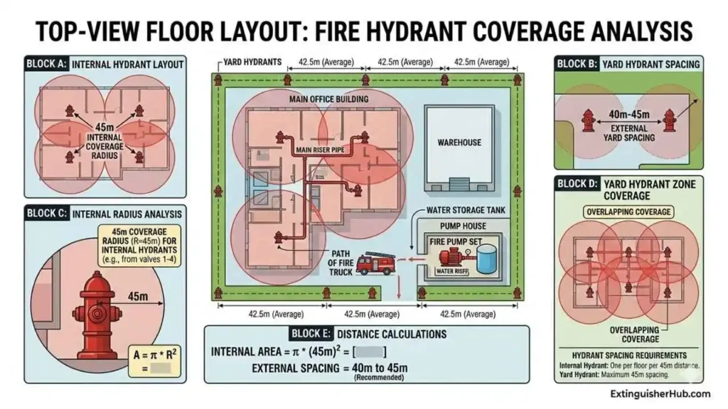
Hydrant Spacing Logic (IS 3844 & IS 13039 Based)
Internal Hydrant Coverage Logic
IS 3844 के अनुसार hydrant system इस प्रकार design किया जाता है कि fire hose और water jet reach के माध्यम से floor के प्रत्येक point तक effective firefighting coverage उपलब्ध हो।
Practically, design करते समय hose length (लगभग 30m) और jet throw को consider किया जाता है, लेकिन actual coverage building layout, obstructions और pressure conditions पर depend करता है।
Placement Guidelines:
- Hydrant valve को staircase या exit route के पास install करें
- हर floor पर accessible location पर hydrant provide करें
- Corridor length अधिक होने पर additional hydrants install करें
- Coverage सुनिश्चित करें कि कोई भी critical area unreachable न रहे
External Yard Hydrant Spacing
IS 13039 के अनुसार external hydrant spacing site layout, hazard classification और required coverage के आधार पर निर्धारित किया जाता है।
Practical design में hydrants इस प्रकार place किए जाते हैं कि site के सभी critical areas effective hose reach के भीतर रहें।
External Placement Guidelines:
- Hydrant को building perimeter और access roads के पास install करें
- Fire tender access clear और unobstructed रखें
- High-risk zones (tank farm, storage area) के पास additional hydrants दें
- Dead-end piping avoid करें – ring main system prefer करें
- Obstructions (walls, racks, machinery)
- Available pressure at outlet
- Hose deployment feasibility
फायर हाइड्रेंट सिस्टम स्पेसिंग लॉजिक
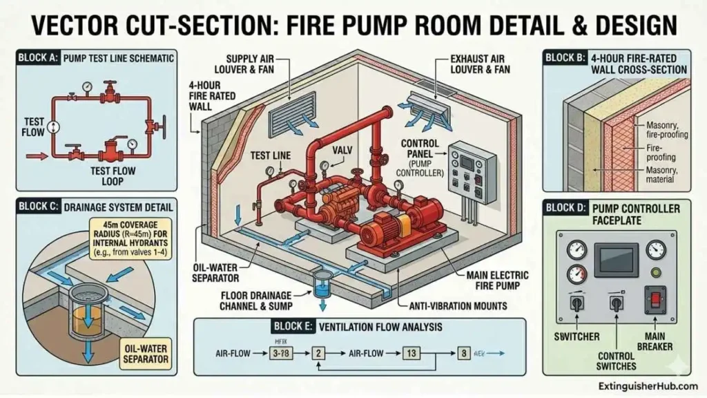
Pump Room Requirements (IS 15301 & NBC Guidelines)
Fire Rated Construction
Pump room यदि building के साथ attached है, तो इसे fire-rated enclosure में provide करना चाहिए। NBC Part-4 के अनुसार adequate fire resistance rating (commonly up to 4-hour, depending on design) system protection के लिए आवश्यक होता है।
Ventilation & Engine Exhaust
Pump room में adequate natural या mechanical ventilation होना चाहिए। Diesel pump के लिए fresh air intake और exhaust व्यवस्था आवश्यक है, ताकि overheating और exhaust gas accumulation से बचा जा सके।
Drainage & Floor Slope
Pump room floor को slope के साथ design करना चाहिए ताकि leakage, testing water और gland drip properly drain हो सके। Water stagnation corrosion, slip hazard और electrical risk पैदा कर सकता है।
Suction Conditions (Very Critical)
Pump suction line short, straight और adequately sized होनी चाहिए। Air ingress, excessive bends और negative suction condition से cavitation risk बढ़ता है, जो pump performance को सीधे प्रभावित करता है।
Access & Operation
Pump room का direct external access होना चाहिए ताकि emergency में fire brigade आसानी से operate कर सके। Access route हमेशा unobstructed और clearly identifiable होना चाहिए।
फायर पंप रूम लेआउट
Installation Guidelines (Practical + IS Based)
Pipe Sizing (Hydraulic Basis)
Pipe sizing हमेशा hydraulic calculation (flow + pressure requirement) के आधार पर करें। Riser और main headers का diameter system demand के अनुसार select किया जाता है, जबकि branch lines outlet requirement के अनुसार निर्धारित होती हैं।
Design velocity सामान्यतः ~1.5 से 3 m/s के बीच रखना बेहतर होता है, ताकि friction loss और water hammer risk नियंत्रित रहे।
Valve Placement Strategy
System reliability और maintenance के लिए proper valve layout आवश्यक है:
- Isolating Valves: Zoning / sectional isolation के लिए
- Non-Return Valve (NRV): Pump discharge line पर backflow रोकने के लिए
- Air Release Valve: High points पर trapped air निकालने के लिए
- Drain Valve: Low points पर system draining के लिए
Incorrect valve placement से hydraulic imbalance और maintenance issues हो सकते हैं।
Suction Condition & NPSH
Pump suction line short, straight और adequately sized होनी चाहिए। Suction conditions को इस प्रकार design करें कि cavitation risk minimize हो।
Excessive bends, air ingress और poor suction layout pump performance को प्रभावित करते हैं।
Hydrostatic Testing
Installation के बाद piping system का hydrostatic test करना आवश्यक है।
- Test pressure: Working pressure से higher (as per design / code)
- Test duration: Sufficient holding period (project specification के अनुसार)
- No visible leakage
- Pressure stability acceptable limits में होना चाहिए
Testing से पहले system को properly fill और air purge करना आवश्यक है।
Maintenance & Testing Schedule (IS Based Best Practice)
यह maintenance schedule भारतीय standards (IS Codes) और NBC guidelines पर आधारित है। Official standards देखने के लिए: BIS Official Website
Daily Checks
- Jockey pump pressure और system pressure gauge reading verify करें
- Fire water tank level check करें
- Pump room ventilation, leakage और cleanliness inspect करें
- Diesel pump fuel level और lube oil condition check करें
Weekly Testing
- Diesel pump को manual mode में run करें (recommended duration: ~10–15 minutes)
- Main electric pump auto-start simulation (pressure drop test) करें
- Battery voltage और charger condition verify करें
- Control panel alarms और interlocks check करें
Monthly Inspection
- Hydrant valves और landing valves operate करके check करें
- Hose reel unwinding और nozzle condition verify करें
- PRV settings और outlet pressure check करें
- All isolating valves correct position में हैं यह सुनिश्चित करें
Quarterly / Half-Yearly Checks
- Pump performance (flow & pressure) verify करें
- Electrical connections और control panel inspection करें
- Diesel engine servicing (filters, coolant, belts) करें
Annual Testing
- Full system performance test (flow + pressure verification)
- Hose hydrostatic testing (IS 636 reference)
- Pressure gauge calibration
- Complete fire safety audit और documentation review
Detailed checklist के लिए देखें: fire safety audit checklist
Cost Overview (Indicative Guide – Non-Definitive)
Fire Hydrant System की लागत पूरी तरह engineered design पर depend करती है। यह केवल equipment cost नहीं बल्कि complete hydraulic infrastructure होता है। Design standards और compliance के लिए देखें: BIS Official Website
Key Cost Factors (High Impact)
- Pump Capacity (Flow + Head): Higher capacity pumps → higher electrical + civil cost
- Building Height: Static head बढ़ने से pump rating और piping cost बढ़ती है
- Hazard Category: Industrial / high hazard projects में higher flow requirement → higher system cost
- Piping Network Length: Larger layout → more material + installation cost
- Water Storage Requirement: NBC norms के अनुसार tank capacity cost को directly affect करता है
Pump & Infrastructure Cost Impact
High head fire pumps के साथ additional infrastructure required होता है:
- Heavy-duty foundation
- Higher motor capacity & electrical panels
- Stronger piping supports & anchoring
High-Rise Cost Additions
High-rise buildings में additional components शामिल होते हैं:
- Pressure Reducing Valves (PRV)
- Multiple risers / zoning
- Higher storage tank capacity
- Advanced control & monitoring system
Automation & Control Systems
Fully automatic systems में fire alarm integration, sensors, auto-start logic और control panels शामिल होते हैं। Automation system reliability बढ़ाता है लेकिन initial investment भी बढ़ाता है।
AMC (Annual Maintenance Cost)
Fire Hydrant System का lifecycle cost installation तक सीमित नहीं है। Annual maintenance, pump testing, inspection और audit compliance ongoing खर्च का हिस्सा
My Final Thoughts – Real Field Insights
यह insights field experience और Indian fire safety standards (NBC & IS codes) पर आधारित हैं। Official reference के लिए देखें: BIS Official Website
Fire Hydrant System केवल pipe network नहीं है। यह एक complete engineered hydraulic system है जिसमें pump selection, pipe sizing, friction loss calculation और residual pressure balance एक-दूसरे से directly जुड़े होते हैं।
अधिकांश system failures गलत assumption के कारण होते हैं — “High pressure pump लगा दो, सब ठीक रहेगा” यह approach technically गलत है। Reliable fire protection के लिए detailed hydraulic calculation अनिवार्य है।
Field observation में सबसे common failure diesel pump testing neglect है। Weekly testing skip होने पर battery discharge, fuel degradation या engine seizure हो सकता है। Emergency के समय यही primary failure point बनता है।
Hydrant system को केवल installation mindset से न देखें। हमेशा यह evaluate करें — “Emergency condition में system कहाँ fail हो सकता है?”Regular inspection, pressure verification और preventive maintenance system reliability सुनिश्चित करते हैं।
Trusted Sources & Technical References
Indian Standards (BIS)
- IS 3844 – Internal Fire Hydrant & Hose Reel Installation
- IS 13039 – External Yard Hydrant Systems
- IS 15301 – Fire Fighting Pump Installation & Maintenance
- IS 9668 – Water Supply for Fire Fighting
- IS 636 – Flexible Fire Fighting Delivery Hose
- IS 903 – Branch Pipe & Nozzle Specification
Official standards और latest revisions के लिए देखें: Bureau of Indian Standards (BIS) Official Website
National Building Code (NBC Part-4)
- NBC Part-4 – Fire & Life Safety Requirements for Buildings
NBC (latest revision) access के लिए: BIS – National Building Code Reference
International Standards (Reference Only)
- NFPA 14 – Standpipe and Hose Systems
- NFPA 20 – Installation of Stationary Fire Pumps
International benchmarking के लिए: NFPA Official Website
Frequently Asked Questions
Fire hydrant system में minimum pressure कितना होना चाहिए?
NBC Part-4 के अनुसार hydraulically remote hydrant पर minimum 3.5 bar residual pressure आवश्यक होता है (light hazard buildings के लिए)।
Ordinary और high hazard projects में effective fire control के लिए सामान्यतः लगभग 4.2 bar या उससे अधिक design pressure consider किया जाता है।
Fire hydrant system और fire sprinkler system में क्या अंतर है?
Fire hydrant system manual firefighting के लिए होता है, जहाँ trained personnel hose और nozzle के माध्यम से पानी discharge करते हैं।
इसके विपरीत, fire sprinkler system एक automatic system होता है जो heat detect होने पर स्वयं activate होकर आग को प्रारंभिक stage में नियंत्रित करता है।
Fire hydrant system का pump head कैसे calculate करते हैं?
Pump head = Static head + Friction loss + Residual pressure + Suction lift।
Building height, pipe length और required pressure के आधार पर detailed hydraulic calculation किया जाता है, जिससे सही pump selection और system performance सुनिश्चित किया जा सके।
IS 3844 क्या define करता है?
IS 3844 internal fire hydrant और hose reel system की installation, spacing, testing और maintenance requirements define करता है। इसमें 45m coverage logic (30m hose + 15m jet reach) और minimum pressure requirements शामिल होते हैं, जिससे effective fire-fighting सुनिश्चित हो सके।
Fire hydrant spacing कितना होना चाहिए?
Internal hydrant के लिए coverage लगभग 45m (30m hose + 15m jet reach) माना जाता है, जिससे किसी भी point तक effective water reach सुनिश्चित हो सके।
External yard hydrants सामान्यतः 40–45m centre-to-centre spacing पर लगाए जाते हैं, ताकि पूरे area में uniform fire coverage मिल सके।
Diesel pump क्यों जरूरी है?
Power failure की स्थिति में fire hydrant system को pressure देने के लिए diesel pump automatic backup के रूप में काम करता है।
यदि weekly testing नहीं की जाती, तो battery failure, fuel issues या engine malfunction के कारण emergency के समय system fail हो सकता है।
Hazen-Williams formula क्यों use होता है?
Fire hydrant system piping में friction loss calculate करने के लिए Hazen-Williams formula widely used होता है।
यह practical और field-friendly method है, जिससे realistic pump selection, accurate pressure drop calculation और overall system hydraulic balance सुनिश्चित किया जाता है।
Fire hydrant system maintenance कितनी बार करना चाहिए?
Daily pressure check, weekly pump testing, monthly valve inspection और yearly hydraulic audit recommended हैं।
Proper maintenance और नियमित testing ही fire hydrant system की long-term reliability और emergency readiness सुनिश्चित करते हैं।

5 thoughts on “Fire Hydrant System क्या है? Types, Design, Pressure Calculation & Installation Guide (IS 3844 & NBC Part 4)”